© Geoff Battick
Compression ratios and squish band clearances are terms you will here if you hang around a two stroke tuner long enough. Historically, compression has always been a concern, but the effects of cylinder head squish design is a relatively new subject. The most basic concern in regards to the compression ratio (CR) is to at least maintain the stock CR if you have modified the exhaust ports opening timing by raising the upper edge of the port.
A quick mathematics problem will show you that if you eliminate one or two millimetres in height from a cylinder (I'm talking about a cylinder that holds liquid) you will decrease it's volume. Your engines' cylinders suffer the same affect when you raise the exhaust port. So now you are shoving less mixture into the same sized combustion chamber, which will yield a lower CR. So you must in turn reduce the size of the combustion chamber volume (CCV) to compensate for the loss of cylinder volume (CV).
Here is the formula for computing Compression Ratio: CR= (CV+CCV) / CCV
must measure the CCV physically(called " cc'ing " ), which requires a Burette (and a plate of Plexiglas with a small hole drilled in it if you are measuring with the head off the engine) or you can use a syringe, but the Burette is much easier and much more accurate. I use a burette and a stand built for the job.
With the engine assembled, you run the piston up to TDC and use your burette to fill the combustion chamber with oil up to the level of the very bottom of the spark plug hole. You will need to have the engine pretty close to level to do this right (like out of the frame!), and a thin coat of grease on the top ring helps prevent leaks. Record the amount of oil in cc's it took to fill the combustion chamber.
(pi) times the (bore (in mm.)squared) times the height(in mm.) of the cylinder from the top of the exhaust port to the gasket surface, then divide that figure by 4000. I could tell you to look it up, but I'm a nice guy, so Pi is 3.142 for our purposes.
Plug these numbers into the formula and you will know your engines CR. If you then measure the CCV of just the head alone(off the engine) and subtract from that number the one you got with the head on the engine and then subtract 3.21( the volume of an RD350 head gasket) you will get the dome volume of the piston. Now you have all the numbers you need to cut the head to obtain whatever CR you wish.
Unfortunately, due to the shape of a typical two-stroke combustion chamber, it is very difficult to simply calculate an amount to skim off the head to re-adjust your CR. You must cut a bit, cc the head, and cut a bit more if the CCV is not what your calculations show you require.
Remember to write down the amount of each cut, so you will know how much to remove when you need to duplicate this for the next head. You may eventually end up cutting so much off that you have changed the entire contour of the combustion chamber. You will need to restore it to it's former shape, while still maintaining the correct volume.
As you can see, it takes practice and time and skill with a lathe. I am not that skilled (yet) but I know a machinist by trade who is, and we do the work together.
What CR to use is a matter of personal preference and how much of a grenade you want to make your engine. The usual limit most tuners agree on for an air-cooled engine is 7:1. (note: this is the "effective", or "trapped" CR, measured from the point of exhaust port closing, as opposed the full, or "swept" CR like 4 strokes use where you use the full cylinders volume at BDC.
This is why people new to 2 strokes look at spec sheets and wonder why the CR's quoted are so low.)6.5:1 is the lowest you'll really want to use. Up to and at this level, you will have few compression related problems if you use a good fuel. A quick and easy test is to do a compression test on your assembled engine using a good compression gauge. Put the gauge in the plug hole, hold the throttle wide open and kick the over hard until the needle on the gauge stops climbing the scale. Up to 150psi and you are fine. That is approx. a 7:1 ratio. If it is way low, like 130, and you know your rings are good, it's time to raise that CR.
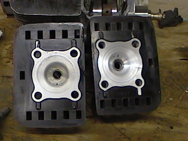
This set of heads has had the gasket surface machined to raise the compression ratio, and the combustion chamber has been machined to maintain the correct squish clearance and chamber diameter. This is typical of the mods done before the concept of fine tuning the squish area was discovered. The squish area itself has been left unmodified.
Some people push the compression up higher and can get away with it. They are good at jetting and reading plugs, use real race gas, are mindful of the ignition timing, and have well designed combustion chambers to take advantage of Squish tuning. This is a concept that first saw daylight in the '80's and is now SOP for serious tuners and designers. It is a design type that fine tunes the whole combustion process and aids reliability in a highly tuned engine.
I first read about it many years ago in article by Kevin Cameron, in a technical analysis of the TZ250U, new that year. He mentioned briefly how Yamaha had experimented with different squish area widths in attempts to aid acceleration out of the turns.
Then one year in the usual mad rush to get ready for season opener we were cutting heads on the lathe and checking compression and had to settle for a funny looking chamber shape (it was about midnight, as I recall) that gave us the compression we wanted. The funny looking part was that the squish area itself (the flattish area that surrounds the actual bowl where the plug end protrudes and extend to the gasket surface) was very narrow, maybe about 12mm in width, with a large bowl in the centre.
Conventional wisdom from the '60's on was that the squish area should be about 50% of the chambers area, like you see in a stock RD350 head. So our narrow squish area looked very odd. Well, the engine ran like a rocket, making big power up until the pipe stopped working, and never ever again gave us a hint of detonation or any compression related problems. Even the tops of the pistons looked better as far as heat and burn patterns were concerned.
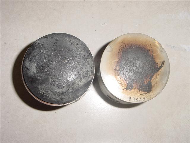
Piston on the left came from a motor using a conventional head design. It has suffered some detonation as shown by the small pieces of carbon that have been knocked off the centre of the dome. Note how the baked on stuff extends all the way to the edge of the dome in parts. The piston on the right was used with a well developed squish design head. The area of maximum heat has been confined to the centre of the dome. No carbon and oil residue approaches the sides of the dome at all, indicating no mixture is being trapped there and burning on. You can also see evidence of the flow pattern in the cylinder by reading the shading on the dome. The cooling effect of the flow from the secondary transfer ports is very easy to see in the two very light coloured small areas at the top of the piston. This is what you like to see when you remove the heads from your motor.
Later that season I was rereading old tech stuff, as I am prone to doing, and I came upon that old article again and once I saw the accompanying picture the proverbial light bulb went on! Same shape as mine!! So next race meeting Kevin C. was perusing the pits (and probably grimly wondering why so many people bother playing with these hopeless toys) so I mentioned my discovery to him and he nodded knowingly in a agreement. So I had confirmation of my discovery and knew the results were not a fluke. What we had done was to get what is known as the squish velocity, or "MSV", in the appropriate range for our engines design parameters. Squish velocity is measured in meters per second (m/s) and the range for the combustion chamber shape we are dealing with in the RD design family is 15 to 30 m/s.
Factors that affect MSV are: Bore, Stroke, Con rod length, RPM at peak HP, exhaust opening timing, compression ratio, squish clearance, and squish area ratio. I use TSR (Tom Turner) programs to design my head configurations, and they do a great job. They also confirmed my original narrow squish design. In the simplest terms, MSV tuning influences jetting requirements and fine tunes the powerband and helps eliminate detonation. One thing that anyone can check on their engine is the squish clearance. This is a measurement of how close the piston gets to the squish area of the head when the piston is at TDC. This has a fairly significant affect on power and detonation control. Gordon Jennings wrote a great piece on this in Motorcyclist magazine Feb. 1995, and explains it in his long out of print two stroke book.
Dale Alexander also explains it well in his RD tuning articles in the ACTSO archives. Basically, any charge trapped in the squish area (between the piston and squish area of the head) does not burn, due to localised cooling from the heads material. So what you want to do is to keep that amount of unburned, thus unused (meaning it's just along for the ride and does not make any power) charge minimised. You get the gap (squish clearance) reduced to a safe amount so the piston does not whack into the head at max rpm. That gap is usually in the .030-.040" range. This squeezes all that once unburned(when the gap was.060") charge into the bowl proper where it gets burned with the rest of the mixture and helps create power.
The easy way to measure the clearance is to use electrical solder which is cheap and always in stock at Radio Shack and will not do funny things like modelling clay can. Do not get the real skinny stuff like.020", as it is not thick enough to use. You will also need a calliper to actually measure with. This procedure is done with the engine assembled and spark plugs removed. Unroll several inches of solder (like 5-6) and put approx. a 90deg. bend in it about 1.5" from the end of the solder. With the piston near BDC, stick the solder in the plug hole pointing towards the exhaust side of the cylinder.
With a little practice you will feel when the end of the solder hits the cylinder wall just below the gasket surface of the head/cylinder joint. Now using whatever tool it takes on the end of the crank or the kick lever, turn the engine over once. You will feel the piston contact the solder when it hits TDC, but keep turning until the solder is free to be removed.
Hopefully you will see that the end of the solder has been crushed (if not the gap is bigger than the solder diam. and you will need to get thicker stuff, maybe plumbing solder, and you know you'll need a head cut for sure) between the piston and squish area of the head. Measure the squished solder and write the number down. Now repeat the procedure until you have four measurements taken approx. 90deg apart around the head.
Hopefully the numbers are all within .002-005" of each other, but it is very common to have one side of the heads measurements be different from the opposite sides due to slight variations in the head castings, and due to the fact that the stud and head design allow the head to "float" until it is torqued down, each time you torque it it sits in a slightly different position on the cylinder giving fairly large variations in squish clearance.
Now you can average out the four numbers and get your clearance. If it is over .040 you'll need to make a cut to get down to at most .040" clearance. The step in a stock head usually measures to be about .018" on all the stock parts I've seen. The standard 350 head gasket is .040" thick. So you can subtract the .018 from your measurement and see what clearance you will wind up with if you just cut the step out of the head. Hopefully it will be in the useable range. If not you'll need to get into fancier tricks which I may explain someday.
One easy cheat is to get some head gaskets made up in thinner cross section to get the desired clearance. Remember, you cannot do anything about the rod length or the pistons height, but you can modify the cylinders, gaskets and heads. Also be sure to keep in mind the effect that removing metal from the head has on your compression ratio!
To further fine tune the MSV (remember that?) you will need a program to calculate it from the data aforementioned data. Some guys have programs for this on the Web and you can hunt them down, or get the TSR program like I use. I like the TSR program because it indicates the octane needed for each compression ratio, and it give a cranking pressure figure in PSI which will come very close to matching the actual results you will see from your compression test.

|
 |
|
|
|