Note:- These originally appeared in a series of articles in the US-based " Antique
Air-Cooled Yamaha Two-Strokes club newsletter". It has been translated into XHTML by Geo of K.G.B. of T & T. with the
permission of the author
In the past couple of issues of the newsletter, Doug Johnson had been doing a credible job of explaining heat, race fuel
and the likes. Dale enjoyed, what he had read, his past racing experience with RD-350's, and this has compelled him to write these notes.
So with no further ado here is his 2 cents worth......
The Art of Squishing Things Till They Give (Power), Part 1
When I started racing RD's, the fast guys on the west coast were Alan and Dain Gingerelli, Dick
Fuller, Scott Clough and Bob Tigert. They were fast at tracks like Sears Point, Riverside and
Ontario. I was just a wee pup of eighteen and had a lot to learn. By the time I left racing, it
took Yamaha's then latest creation, the FZR 400, to make my fifteen year old RD-375 obsolete.
What I mean by obsolete was that I had been relegated to finishing 7th with six FZR 400's in
front of me. Not wishing to spend $5000 to ''purchase' trophies, I hung it up. What's important
here is the fact that I would very much like to pass on the knowledge the I have accumulated
during all those years and as Doug has more or less started the ball rolling with his articles
on heat, I see no reason to break stride.
Stone Knives and Bear Claws
Way back when Mt. Everest was a foothill and two-strokes only came in one, two or three
cylinders, companies like Denco Engineering and Hot Bike Engineering were running Kawasaki
triples regularly at Fremont Dragstrip. Tony Nicosia would run the Kaws all the way down to the
end on the back wheel, severely stressing the wheelie bars. Quite a sight to behold. And when
the bikes were brought back to the pre-staging area, a curious ritual would begin. Out came the
pressurized water sprayers to hose the cylinders, heads and cases off. Some wise-ass would
invariably make a comment like 'It don't matter how much they water them things, they ain't
gonna grow any faster'.
My own experience with road racing was just beginning to develop. I was soon to observe that
the RD would run pretty strong in 6th gear out of one corner, only to be reduced to 5th gear
and finally 4th gear by the end of the race. The engine was consistently losing power as the
race progressed. Something was overheating, BUT WHAT? Suzuki had Ram-Air heads on their 380 and
550 triples, after-market water-cooled heads were available but even the factory water pumpers
were having a like problem so what was the point?
To make matters really confusing, all manner of porting ideas were being tried, but everyone
was going pretty much the same speed or slower. So it would seem the whatever the problem was,
it was related to heat, the development of power and the amount of time that the power was
being used.
So, What IS Going On?
At this time, the mid to late 70's, state of the art for porting and compression was pretty
much in it's infancy. Raise the exhaust port to 28 m.m., trim .020" off the head, add some
richer jetting and let's go racin'. This yielded a moderate increase in power and compression
which, if checked by a gauge, was about 150 p.s.i.. As my quest for knowledge grew and my
desire to extract reliable power increased, I started looking down other avenues to expand my
understanding of what was needed to make heaps and heaps of consistent power.
A not so obvious
place to look turned out to be car racing. Even though one might at first think the four-stroke
engines have little in common with two-strokes, I was soon to prove myself wrong. With the
exception of how gases move in and out of cylinders, both designs are plagued with much the
same problems and the first lesson I learned about heat and how to control it led me to
investigate quench bands or squish bands as they are known to us.
The squish band is the area along the outside edge of the head that is more or less flat or
matches the angle of the crown of the piston closely. Its purpose is two fold:-
1) it acts to create a mixing of the charge as it is compressed by the piston. This helps to make a more
homogeneous mixture that burns faster with less ignition advance.
2) when properly set up,
the squish band acts to cool the charge and the end gases to help eliminate detonation. THIS is
the really important aspect of the squish band as it relates to a two-stroke.
It acts to cool the charge. Weren't we just wondering where all this damaging heat was coming
from? I've looked at a ton of pistons and noted early on that a lot about heat can be learned
by turning the piston upside down and looking at the area under the crown on the inside of the
piston. Good running bikes had a very light brown color that was glossy. Better running bikes
had a much larger area that covered the entire underside of the crown and was much darker in
color, but still glossy. On bikes that didn't run that hard, this area had turned flat
black.
This is perhaps one of the best areas to keep an eye on the heat health on an engine, so it's
important to understand what information has been given to us here. Oil, whether in a
four-stroke or two-stroke, is being churned up by the crankshaft and is being thrown against
the underside of the piston crown. The heat of combustion moves from the chamber side of the
piston crown to the underside as the piston tries to rid itself of the heat before melting. It
is the presence of this heat that bakes (or burns) the oil onto the underside of the piston. A
little heat, a small light colored area. Too much heat and the oil burns carbon black. A very
useful indicator indeed.
But a function of the heat that is unique to a two-stroke is that the worst of its effects is
yet to be felt. When gases are heated they expand, and if the container that they are expanding
into happens to be sealed, pressure rises. Well, isn't the crankcase of a two-stroke sealed for
the time needed to build pressure to start the scavenging cycle? Yes and here's the rub. As the
piston crown grows hotter, the underside radiates this heat into the crankcase, increasing the
pressure to such an extent that when the intake port opens, the pressure inside the case is
momentarily higher than that of the incoming charge and everything stalls for a brief moment:
Brief for all things but the engine. It WILL NOT fully charge the case and as a result the next
scavenge event will not fully charge the combustion chamber and the engine is now not
developing the power it did when things were cooler. Hence, Tony Nicasia waters his bikes to
try and battle this problem externally.
What can be done to take care of this problem internally can best be summed up be understanding
some of the nature of combustion and the physical properties of the engine. This would be a
good time to glance at Figure 1. This drawing represents to the best of my memory a cross section of an RD-350. It could be any engine actually. It should be fairly easy to make out the
cylinder, head, piston, gasket, bolts, etc. The boxed in area is the area that I wish to spend
some time talking about 'cause this is where all the problems regarding heat begin.
Figure 2.is
a blowup of this area so move along and be quick about it! Along the left side of Figure 2.
there is a darker area that corresponds to the head gasket. On an RD-350, the gasket is .040";
thick. The step just above the gasket represents the .020" step that one will find in a stock,
unmodified head. Together, these two figures add up to a value of .060". Keep this in mind,
because these very small values will become VERY important in a moment. For future reference,
this .060" is properly known as piston/head clearance and will be called such.
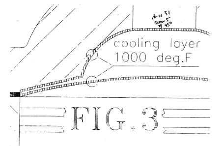
Figure 3. shows an additional dark area that encircles the combustion chamber. This shaded area
represents all the area of the head, piston crown and cylinder wall that is exposed to the heat
of combustion at T.D.C.. I like to call this area the "boundary cooling layer" area. Please
note as well that I have given a value of 1000 degrees to this layer. For sake of argument,
let's say that the fuel gets into trouble (detonation) at any value greater than 1000 degrees.
This is not the true temperature involved here, but for ease of arithmetic, let's keep the
numbers round. The real numbers aren't important, just the concept. This boundary layer depicts
the physical effect that occurs when a hot gas is in proximity to a cooler object: the
combustion gas is cooled by the presence of the cooler head, piston, etc.
By experimentation, I
feel comfortable saying that this layer is usually no thicker that .020". As the piston has a
boundary area that is .020" thick and the head is .020" thick as well, it doesn't take a rocket
scientist to see that the area between the two cooled surfaces is .020" thick AND is uncooled
by the boundary effect!!! This is the area where the problems with heat start. The combustible
gases all the way out to the left side of this area are known as "end gases". When the gases in
the main portion of the chamber are ignited, several things happen at once:-
1) the spark starts the actual chemical reaction that is combustion
2) the temperatures and pressures build quickly
3) the flame front moves rapidly away from the spark plug.
As the flame front moves to the end gas area, pressures rise quickly even though the piston is
descending. At some point, the pressures and temperatures are great enough that the end gases
will spontaneously ignite. This is known as detonation. When the end gases ignite in this
fashion, the pressures in this area grow to tremendous values leading to piston fractures,
hydraulic type stress failure of small and big end needle roller bearings and other not so nice
things.
Detonation can be inaudible what all with the racket that the intake, exhaust, piston
slap and ring flutter can make, so damage can be occurring and pistons overheating without any
warning to the rider. Assuming that the ignition is timed to a reasonable value and the octane
rating of the fuel is sufficient for the use the engine is seeing, one of the only other things
that can be done to reduce the possibility of detonation is to reduce the piston/head clearance
to .035".
That way, the boundary cooling layers overlap and all end gases in this problem-prone
area should be reduced in temperature to a level below the "auto-ignition" point.
When this happens, the piston crown is no longer heated to such an extreme extent, the charge in the
crankcase is reduced in temperature reducing the pressurization and allowing a more complete
filling and power goes up and stays longer as a result.
Looking back to Figure 3,, note once again that the boundary layers are .020" each and the
clearance between the layers is .020" as well. If one removes the step in the head which is
approximately .020", the piston/head clearance will be down to .040" but my experience has been
that .030" to .035" works the best. I think I'll let you all stew on where to lose that other
.005"/.010" until the next issue. But rest assured the wait will be worthwhile as I'm just
beginning to scratch the surface of go-fast stuff.
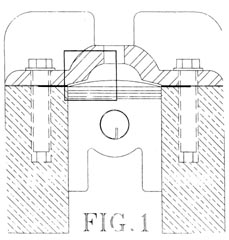 What can be done to take care of this problem internally can best be summed up be understanding
some of the nature of combustion and the physical properties of the engine. This would be a
good time to glance at Figure 1. This drawing represents to the best of my memory a cross section of an RD-350. It could be any engine actually. It should be fairly easy to make out the
cylinder, head, piston, gasket, bolts, etc. The boxed in area is the area that I wish to spend
some time talking about 'cause this is where all the problems regarding heat begin.
What can be done to take care of this problem internally can best be summed up be understanding
some of the nature of combustion and the physical properties of the engine. This would be a
good time to glance at Figure 1. This drawing represents to the best of my memory a cross section of an RD-350. It could be any engine actually. It should be fairly easy to make out the
cylinder, head, piston, gasket, bolts, etc. The boxed in area is the area that I wish to spend
some time talking about 'cause this is where all the problems regarding heat begin.
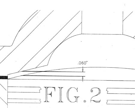 Figure 2.is
a blowup of this area so move along and be quick about it! Along the left side of Figure 2.
there is a darker area that corresponds to the head gasket. On an RD-350, the gasket is .040";
thick. The step just above the gasket represents the .020" step that one will find in a stock,
unmodified head. Together, these two figures add up to a value of .060". Keep this in mind,
because these very small values will become VERY important in a moment. For future reference,
this .060" is properly known as piston/head clearance and will be called such.
Figure 2.is
a blowup of this area so move along and be quick about it! Along the left side of Figure 2.
there is a darker area that corresponds to the head gasket. On an RD-350, the gasket is .040";
thick. The step just above the gasket represents the .020" step that one will find in a stock,
unmodified head. Together, these two figures add up to a value of .060". Keep this in mind,
because these very small values will become VERY important in a moment. For future reference,
this .060" is properly known as piston/head clearance and will be called such.