Mike Hammer asked Dale to update the info for porting on RD/RZ series engines. As the Information is by nature fragmented I have put the whole lot on one web Page and one PDF to make it easier to research
First of all, I am very sorry, but because of the number of people calling and saying things
like "Well, I have only followed one of your tips and my bike isn't much faster, can you
help?", I have decided to take my contact info off this page. There are just too many lazy
people out there. So, the following is offered "as-is". If you follow the advice your bike will
be fast. If you don't, it will be slow.
Read These...
A lot of what I have to say involves info that needs a fairly good grounding in engine
performance theory. I found the following books to be very helpful in gaining that
knowledge.
1). The Chevrolet Racing Engine by Bill Jenkins
2). Smokey Yunick's Power Secrets by Smokey Yunick
3). Race Engine Prep by Wadell Wilson
4). Performance Tuning in Theory and Practice: Two Strokes by a A. Graham Bell
There are many others out there, but these are written by people that have actually built
engines that win. As far as four stroke vs. two stroke, there is cross-over technology that
applies to both and reading the books will only help you in the long run.
As well, I have written some recent articles on heat related power loss in two strokes and carb
modifications that are very relevant to this info. Mike Hammer has turned these into HTML & Geo updated them into XHTML and
they are available here. For more info on RDs I recommend that you contact:
Doug Johnson
Assoc. Of Classic Two Stroke Owners
1-509-453-1976
Request volume 3 #3, volume 4 #1 and 2.of the " Expansion Chamber "News Letter. These relate to heat and power loss.
Request volume 4 #3. This outlines modifications to 28mm Mikuni's for additional power and
driveability.
Nuts and Bolts
I do all my port timing with a degree wheel as who knows what the last crazy person did to your
barrels, I'm only concerned with what the current crazy person is doing! When it all comes
together, the only thing that matters is where the piston is when it is time for a very
specifically timed event to occur. The only way to ensure this is to work with a degree wheel.
Get a good quality one and learn how to find TDC with the positive stop method.
Squish Clearance
Squish clearance is very important to get correct and every effort should be made to get the
right values. When this is done correctly, the engine will develop more power and be more
resistant to over-heating and detonation. The value that I like to use on the RD/RZ series
engines are .030" to .035". The info in Doug Johnson's ACTSO articles listed above will
describe what the desired end result is and how to get there. The angle of the squish area of
the head is best set to 14 degrees.
Compression Values
Because I set the squish band much closer than what comes out of the box, I always ran pretty
high compression for air cooled engines, on the order of 175 psi. I would check this when the
porting was done and the final adjustments were being made to the head. The squish clearance
will have been set and confirmed by this point. I would assemble the engine and place a good
quality compression gauge (with a weak schraeder valve) in the spark plug hole and boot the
kick-starter over (no carbs attached) until the highest value was reached. If the value was
lower than what I wanted, then the head would have to be surfaced again, the squish band
redefined and tried over. The idea was to reduce the volume of the head to bring the pressure
up to what was wanted. If the compression value was too high then the head would need material
removed from the hemi-shaped portion nearest the spark plug. DON'T remove material from the
squish angle area. This will reduce the compression but will also increase the clearance that
you tried so hard to set to .030".
Pipes and Carbs
We have used these specs with Toomey pipes for top-end (11,500 red line) and Lassek pipes for
more mid-range(10,500 red line). They are a very forgiving set of ports. We have also used 29mm
carbs to 36mm carbs with great results. I personally like the 29mm carbs (bored set of stock
R5/RD) as they have a very wide power band with only a minimal loss of top end. I would stay
away from the TMX style Mikuni's as the needle jet is not a tunable item i.e. not
replaceable.
Unless you want the engine to run worse, do not run open carbs or individual filters. We ran
the stock rubber air boot with a tall K&N filter. This alone was good for a .2 second
decrease in 1/4 mile times along with a 2 mph increase in speed over open carbs. This is nearly
free horsepower. Your out of luck here if you run anything other than stock carbs though.
Mike's note:
( As Bell's book points out, tuned intake length is the important thing here. You
might try long, narrow taper intake horns if you are running non-stock carbs to get the same
tuned length as a stock RD. This helps things considerably though you still lose some bottom
end.)
Geo's note:
Having Taken Bell's advice about tuned intake legth & wanting to use individual K & N Filters I made extension pipes between carb & filter from plastic domestic waste pipe. Take a look at this picture you can just see the grey pipes from the carb going upto the side panels hiding the Filters. Sorry but the pic is a "400% blowup " and the bike is 4K miles away from my desk :[
Carb parts are:
Air jet: 2.0mm
Needle jet: 169 series P2
Pilot jet: 30-35
Jet needle: 5J9
Main jet range: 180 to 230
Slide cut-away: 2.5(stock)
Air screw: 1/4 to 3/4 out
The carb parts are available from Sudco Mikuni 1-213-728-5407
Although Lassek pipes are no longer available from Lassek directly, I have seen posts that list
a source as:
Tommy Crawford
1-909-658-4205
Plug Reading
Part of tuning is knowing how to determine what changes to make and the best way to do this is
to learn the art of plug reading. This took years of observation to figure out a discipline to
reduce this process to a quick and accurate race day drill. I include the following to help.
Forgive the fact that it reads a bit out of context: I copied it from a post I made to a two
stroke list
Been reading the string about plug chops and I thought that I would add my advice as
well.
The first thing that must be understood about 2-strokes (Yam RD's anyway) is that they are
horrible at pumping out the bottom end. Has anyone noticed that when the barrels are removed
the crank is swimming in old oil? This is what was left on the cylinder walls and everything
else when the engine was shut down last and all that oil has to get out of the engine as it
will color the plugs and make things look richer than they really are.
Best thing to do is to go down to a local auto parts store and pick up a box of plugs. Now the
RD's use ND W27xx and NGK B-9xx for racing and these plugs can be had for about .75 cents each.
Those of you with the high zoot rides with the primo-expenso plugs are gonna have to bite the
bullet on this one.
At the races, I would fully warm up the engine for 10 minutes blipping the throttle. Nothing
serious-maybe 6-7 grand. I would do this to get the old oil out of the crank. I would also be using
the old plugs that I had run in the previous race meet main event. After the bike was fully hot
and the exhaust smoke was running clean, I would put in a fresh set of plugs-cost of
$1.50.
Now comes the next most important part. Just before practice starts, warm the bike up again.
When you are released to the track, DO NOT give full throttle to the engine for at LEAST 2
minutes. Dumping a main jet load of pre-mix or straight fuel on a cold plug will color it rich
and quite possibly begin the fouling process that so many are aware of. I start out giving the
engine maybe 1/3 throttle for about 4 corners (at Sears Point) with no more than 6,000. Then I
steadily move up the throttle and rpm until the first straight (about 1 minute into practice).
When the first straight comes up, I roll the throttle on VERY slowly, 6500 shift to 4th, 7500
shift to 5th, 8500 shift to 6th and then bring the throttle up to full slowly. By now the plugs
have been fully warmed up, what residual oil was left in the lower end has been slung off the
crank long ago and what the plugs will see from then on will be much more representative of how
the engine is jetted.
I used to take plugs out of the long-rod motor that were bone white all the way down to a very
faint tan ring at the very bottom of the porcelain which is the ring your looking for. You will
NEVER see that in a plug that is one race week-end old, so get used to throwing away the plugs
often.
I used to have people run over to me and put plugs under my nose with the accompanying question
" How is my jetting" . And looking down at a set of coal black plugs I would reply "Which
race?". If I knew that this person had another set of plugs, I would throw them away and force
him to put a set of new plugs in. A bit extreme maybe but after the bike started to respond to
proper tuning changes a lot of racers learned the value of this philosophy.
So clear out the engine, warm the new plugs up slowly, learn what the plugs are telling you and
change the plugs often.
Although there are very expensive oils out on the market, I have found that either Oilzall or
Golden Spectro Synthetic mixed at a ratio of 32:1 (4oz./gal) worked very well for me under
extreme racing conditions. By extreme I mean full throttle applications for 1/2 to 5/8 mile
long straight-aways common to California race tracks. Piston wear and crank life were always
good. If I had to choose between the two I would use Oilzall because being a castor based oil,
it smells cool!
Now...For The Cool Specs
I have found these specs to work for just about every required purpose. Get yourself a porting
tool, port everything to this stuff and start your own business. I'm not kidding. I used to get
$150-$500 for the info I'm putting out here. So knock yourself out!
Exhaust Opens: 82 degrees after TDC Duration 196 degrees
Exhaust Width: 70-75% of bore (46-48mm). The top edge of the port looks like an oval. This is
not the place for a sharp edge as that will make the power band too sharp. The sides of the
port actually extend over the top of the transfers but sides of the port go from the stock
location on the bottom of the port in a straight line to the side of the port. The best way to
describe the shape of a finished port is to visualize a trapezoid with a curved top edge.
Transfers Open: 64 degrees before BDC Duration 128 degrees
The rear edge of the main transfer is brought back to eliminate the mismatch between the liner
and the barrel. I have used epoxy to remove this in extreme cases. This leaves about 1mm of
cylinder between the main and auxiliary transfer but who cares, it only acts to support the
ring.
Rear Boost Port Width : 20mm This is angled up to make the new height and cleans up really well
in the RZ's. The RD's will need the help of epoxy and then angle back to make the lower edge of
the port at the intake about 50% deeper.
Intake Height: Raise to 1mm below bottom ring with piston at TDC. Can raise to 1mm below
top
ring if top ring is a Keystone type ring and you discard the second ring.
Bottom of Intake: Can go as low as desired, just don't go through to base gasket surface!
Intake Width and Bridge: I believe that it is much more important to provide for piston support
so I don't make the port any wider or the bridge any narrower. There is plenty of hole when you
get done with raising the port.
Lower edge of liner: ONLY in the area of the main transfer lower edge of the liner, remove 10mm
worth of material bringing the edge up closer to the top of the barrel. We want to increase the
area that will allow the scavenge gases to into the main transfer port. DO NOT do this all the
way across. The motor doesn't like it.
RD 400
The best combo to use for a standard 400 would be to use the Daytona pistons as they do not
have the cut-away in the bottom of the exhaust side skirt. Plug the hole above the exhaust port
with a set screw after tapping the hole to accept the screw. Loose the exhaust butterfly valve
on the Daytona (duh!). If you are having the crank serviced, use the Daytona rods as they are
have slotted lower ends and this allows oil to reach the bearings easier. Use early model TZ
(from the B,C,D,E in the 70's) lower end rod bearings. They have silvered cages and free
rollers that reduce friction and heat. By far the weakest link in the 400 is the crank. It is
very heavy and prone to spreading the mag side so welding is a must. The center axle between
the two halves is also very prone to snapping in a high power application. Anything that you
can do with the Daytona to get rid of the flywheel ignition and replace it with a Krober or
Motoplat or anything lighter will help greatly. We used TZ 750 reed assemblies at first and
then went to RZ reeds when they became available. A lot of metal has to come out of the intake
port to do this a quite possibly you will grind through to daylight, but a through application
of epoxy will save the day here.
RD 428
Many of these were built with TZ 750 pistons but the supply dried up and just as well as the
last models had a very short skirt which was bad from a wear point of view. I did make one of
these (66mm bore) with a DT 175G enduro set of pistons. The pin height difference in the
pistons made it necessary to cut 5mm off the bottom of the barrel and re-locate the headers to
prevent dragging them on the ground. What we wound up with was a very potent air cooled bike
that could consistently beat my long rod RD 375 for the win. Of course I had built it for a
very close friend. The only recommendation that I can make is don't give your friends bikes
better than yours.
RD 350
Pretty much everything said about the RD 400 holds true for the older brother, except that we
had head gasket problems. We used a 400 head gasket and finally a TZ 750 cylinder head O-ring
that stopped all the gasket weeping. This is outlined in the articles that Doug has at ACTSO & on THIS SITE
Copper Coat on the copper gaskets works real well for stopping seepage.
Long Rod RD 375
With this motor we used DT 175G pistons from Yamaha to bring to bore to 66mm and displacement
to 375cc. The pin height allowed almost a bolt up assembly when we used the Daytona rods with
TZ bearings. With the change in rod/stroke ratios, the stock cylinders will only need minor
port work to make the figures listed above. If I remember correctly, .070" needs to come off
the top of the barrel to get the squish band right This is the combination that I used for
years to gather tons of trophies. It never blew up. Couldn't kill it. I tried!
Long Rod RZ 375
I only built one of these for my girlfriend (at the time) that was racing in the AFM. In 1988,
she got second in class in Calif. In the 450 Prod. Class. This works. I could never catch her
after I built this one! It is also a little more difficult to pull off. Side thrust washers
have to be made out of Ampco 45 for the lower end of the rod as the Daytona rod is narrower
than the RZ rod. The porting is somewhat tricky too as the ports don't quite line up as they
should, so maybe do some other port work before you tackle this one. With chambers...well it's
too scary to think about. Should be illegal.
Not Another Boring Carb Article!
There has been some questions about bored carbs as of late and I would like to share my
experience.
First off, I feel that the RD, RZ series engines do not have the port time/area needed to fully
use any carb above 34mm to its full potential without suffering serious holes in the powerband
and driveability problems. In maximum power applications with minimal regard for powerband,
34mm works fine. I have had MUCH better results using a modified stock 28mm carb body. The
overall power is down only slightly with a much greater low/mid range power: A better overall
choice for a balanced powerband.
I must add that I never developed my engines for maximum power as my home track was Sears
Point, but my engines didn't suffer at anyone elses hands at tracks like Willow Springs or
Riverside either. I always believed that a balanced combination with smooth power was better
than an engine that wouldn't pull its hat off its head below 8,000 only to wrench the wheel
loose from the ground at 8,001 rpm's.
I preferred to use R-5 carbs when available as the air correction jet was aIready the proper
size and eliminated one step needed in setting up RD carbs, but RD carbs are none the less
fine. There are different models of 350 carbs, short top and tall top and this affects the
choice of cables. I prefer the 350 carbs over 400 (certainly the Daytona) as the idle air bleed
hole in the bellmouth of the carb is sealed with a ball that must come out before any of the
air jet modification/tuning work can be done. Last that I heard, the junction boxes for the
three cables was as rare as hens teeth, but if you pre-mix(HIGHLY recommended) you only need a
two cable junction and these are easier to come by.
SPECS FOR JETTING
Needle Jet: 169 series, P-2, Spray shield cut down to 2mm in height
Jet Needle: 5J9 2nd, 3rd, 4th clip position
Slide cut-away: 2.5 (stock)
Pilot Jet: 30-35
Main Jet: 180-210
Air Correction Jet: 2mm
Carb bore at venturi: 29.5 mm
Idle air screw: 3/4-1 1/2 turns out from bottomed
Works best with at least RZ style reeds. I like metal reeds, so crucify me!
I would like to summarize and add something from my experience of running/boring carbs.
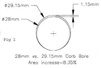
1). Carbs should be bored offset to the venturi centerlineSee Fig 1. A proper setup would
have the boring bar JUST touch the area where the needle jet resides so as to remove as little
material as possible.
2). This is done to prevent an excess of air flow past the slide at the idle position. If the
carb is bored concentrically, too much material will be removed under the slide and the idle
will be too high even with the idle screw removed. The reason that this is owes to the fact
that the slide will rest on the body of the carb and still pass too much air. A high idle was
always a dead give away of cheater carbs at the races.
3). Because of #2, the carbs should be bored on a mill to allow proper X/Y axis offset in
relation the centerline of the venturi. Boring can be done on a lathe, but it takes a four jaw
setup and someone pretty sharp with the lathe.
4). If the setup is proper, the end result is NOT an oval carb bore. Material is removed from
the entire I.D. of the venturi, just more material in some spots(top) than others. CV carbs on
4 strokes are an example of "oval" carbs. 4 stroke carbs are done this way to give good low
load mixing/response with the potential of high air flow during high load conditions. Kinda
like a poor man's 4-barrel carb for bikes. Poor 4 strokes! They need all this help just to get
out of their own way!
5). If boring an extreme amount, the manifold will need to be matched as well.
6).THIS IS THE MOST IMPORTANT PART, SO READ CAREFULLY! If you find that the slide does not
raise high enough to give full opening with the new bore size, be reeeal careful trimming the
top of the slide to allow slide to move farther up. If the slide is trimmed too much, the slide
can lift over the slide guide pin that holds the slide from rotating(by way of the groove on
the side of the slide). If that happens, the throttle will be stuck WIDE OPEN and no amount of
fiddling with the throttle will shut the slide off at that point. Make sure your kill buttons
work and only try full throttle in 4th, 5th or 6th so the bike doesn't got away from you. Just
be real careful trimming the top and check and check and check again.
Great! Now We Have A Lot Of Air, But Dont We Need Fuel?
The 169 series needle jet is a primary type needle and because of this, it needs a larger air
correction jet. The stock needle jet was designed as a four stroke type needle and is known as
a "bleed" type. It is primarily responsible for that hit in the seat of your pants feel at 6
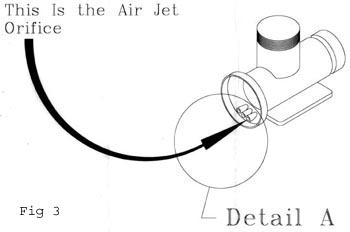
grand. The primary type works much smoother. The passage that needs to be modified is easy to
find. Look at the bell mouth of the carb and find the small hole at the bottom of the mouth
that is in alignment with the needle jet(remove the needle jet for this operation)See Fig.3
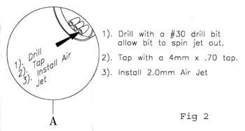
Purchase the 2mm correction jet from Sudco or Rocky. Buy a 4mmX.70 tap and a number
30 drill. Use the drill to drill out the stock .6mm air jet Fig 2. The drill should
catch the air jet and spin it out. Use the tap drill to tap threads into the new hole. Stop
when the tap gets tight as it should bottom in the hole. When finished, insert the 2mm air
correction jet and marvel at how easy it was to turn a street bike carb into a carb with a
racing heritage!
Before installing the 169 series needle jet, the spray bar(shield) must be cut down or the
mid-range circuit will operate too late and screw up everything. With a pair of venier calipers
set to 2mm, use the id measuring portion and mark off a line that is 2mm from the base of the
needle that would be flush with the carb bore. Hold the needle jet in a vise(gently!) and
position the scribe mark in such a way as to use the sides of the jaws as a guide for the
blade. Using just a fine(32 teeth per inch) hacksaw blade, cut just barely away from the line,
leaving enough to trim to length with a fine file.
The recommended main jet size may sound small to a lot of you but it is correct. The reason for
this is due to the primary type needle, the air correction jet change and the way that the
mixture is emulsified. The numbers are different but the dumb engine still sees the same fuel
as when the stock carbs are used with a 280-310 jet. If you don't believe what I'm saying, feel
free to start at 300 and work backwards.
The pilot jet I used was a 30. More modified bikes may need a 35. Air screw set to 3/4 turns
out on my engines. If you feel that this is too rich, turn it out to 1 1/2. If you find your
engine needs to have the screw out further, than lean out the pilot jet.
For a perspective, my engines were 375cc with long-rods, compression set at 175 psi, squish at
.030", timing 1.8-2.0mm btdc, 106 octane, B9HS plugs, stock exhaust with modified baffles(more
flow) and moderate amount of port work. They worked well enough that it took the FZR-400 series
to finally start winning races from me so I think that this carb setup will work well for just
about any RD from street bike on up to full race. I have used the same setup on long rod
RZ-375s for AFM Superstreet racing with great results. If your engine has an unmodified squish
with cut heads, you may need more main jet as a larger amount of jet will be needed to cool an
in-efficient engine.
The beauty of this is that the carbs with modifications can be had for a lot less than a set of
GP Mikuni's and I always believed that it was smart to only spend money when needed and to stay
away from trendy(38mm carbs?).
Part numbers that you need are:
002.165 .... 2.0mm Air Correction Jet
002.296 .... 5J9 Jet Needle
003.261 .... 169 Series P-2 Needle Jet
Lectron Flat slide Carbs
Hi all! Been reading the current string about Lectron carbs and would like to fill out some
info.
Over 20 years ago, I remember having a set of Lake "Fuel Injector" carbs on my Norton Commando
750. I believe this to be the precursors to the Lectron style carbs. The Lake carbs did not
have a float system at all, just a fuel line to the bottom of the carb where the needle would
be. I don't remember how the mixture was adjusted as I never did adjust it! Hey! I was only 16
at the time and not old and smart(assed) like I am now. The carbs didn't qualify for more than
a calibrated piss as far as accuracy but as they were one of the first "smooth bore" designs
out there, they flowed a lot of air so power went up, even if it was crude power at best. And
they looked cool. Exotic. Had to work better if you know what I mean ; )
Posa carbs were a like design so I won't spend any time on them.
Lectron carbs were much the same as well but with two VERY important improvements: a float
system ala Mikuni and a powerjet top end fuel supplement.
Nothing special about the float system. It was a natural progression to correct what Lectron
saw was a weakness in the Lake type carb. It allowed precision in the float level. The Lake was
prone to flooding and hard starting(duh!). The power valve was a new concept at the time and
Lectron was the first carb I remember seeing with a power jet and should be note-worthy in that
fact.
HOW LECTRONS WORK
The Lectrons have a central fuel outlet, that being the needle area. The needles controlled all
fuel now with the exception of the power jet. One of the ideas was to eliminate the rich and
lean spots in the fuel delivery curve as can happen with a multi-area delivery device such as a
normal carb. The other was to make a system that was easy to adjust. Lectron succeeded
brilliantly in one area, failed miserably in the other.
Fuel control was with the needle. A taper was ground into the needle on the side that faces the
intake area of the engine. Needles were graded and marked 5-3, 6-1, 6-2 etc. These numbers were
easy to understand. The first number was the overall richness of the needle. A 5 series was
leaner than a 6 series. The second number was the midrange richness. A -3 was richer than a -1.
The very top end was controlled by the power jet exactly as we understand power jet function
now.
In order to have a "base" point that tuning could be initially set to, a distance was specified
as standard, a datum. This was the length of the needle from the adjusting nut(what would be
the needle clip in a Mikuni) and the tip of the needle that extends into what would be the
needle jet in a Mik. The "needle jet" was not adjustable, much like the TMX style of Mik. The
standard length was 1.945" or something like that. If the length was longer, the overall fuel
was leaner as the taper would be lower and this would allow less fuel for any given throttle
opening. The opposite was true if the needle length were shorter than 1.945". I think that if
you had to go more than 2 turns in either direction, it was time to change the needle for a
different fuel curve. This allowed for the fine adjustment of fuel.
If one were to replace the screws holding the top of the Lectron with snap clips to allow quick
removal of the top, a minor needle adjustment with power jet swap could be made in about 2
minutes for 2 carbs. This was one of the Lectrons strong points.
If jetting was ok in the mid-range but off a bit just before power jet came on, you wouldn't
want to adjust the needle as this would upset the balance with the mid-range. You would select
a needle with a different second number - 1, -3 etc. THIS is where the Lectron failed. The
quality control of the grinding of the needles was such that even though you had two needles
marked the same, it didn't mean that you hade two needles that were the same. At first this
caused all kinds of confusion as one would change the needles expecting a change in a known
area and the engine wouldn't run anything like what was expected. Only after measuring the
needles very accurately at absurdly small stations were we able to ferret out that Lectron
needles were ground by the firm of "Byguess and Bygolly"!
The only way to solve this problem was to carefully hone stone the needles and hope that the
results gave you a pair of needles that could be used together, run them, grade them, and hope
that one was fortunate enough to get a selection after a while. With all this tuning work done
to the needles, it's not hard to see that if one had a good set, they didn't get loaned out at
all(Hey! I need as set of 6-2's. Got any I could borrow for this race?) Might as well part with
your right arm once your friend figures out your needles work better than his!
On of the other strong points was that without a pilot circuit, the Lectrons could be run at
absurd angles(35 deg) compaired to the Mik's. This allowed the carbs to be mounted to a
straight manifold on the Super-street RD's for a more direct shot at the intake. If a Mikuni
was mounted this way, it would flood horribly under hard braking as fuel poured out of the
pilot circuit. This was not a problem with the central fuel point on the Lectron's.
But time moves on and the quality control finally caught up to Lectron(and some other problem
with finances or something). Carb technology advanced as well and we have very good, though
expensive stuff now that needs computers to do all the thinking where us mortal humans did it
before. This is progress...I think.
Good hunting...
Dale Alexander
For further updates on Ceramic coating check here
For further details E-Mail:- KGB-Racing at Saltmine dot Org dot
UK
 Purchase the 2mm correction jet from Sudco or Rocky. Buy a 4mmX.70 tap and a number
30 drill. Use the drill to drill out the stock .6mm air jet
Purchase the 2mm correction jet from Sudco or Rocky. Buy a 4mmX.70 tap and a number
30 drill. Use the drill to drill out the stock .6mm air jet